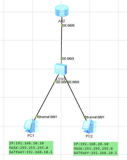
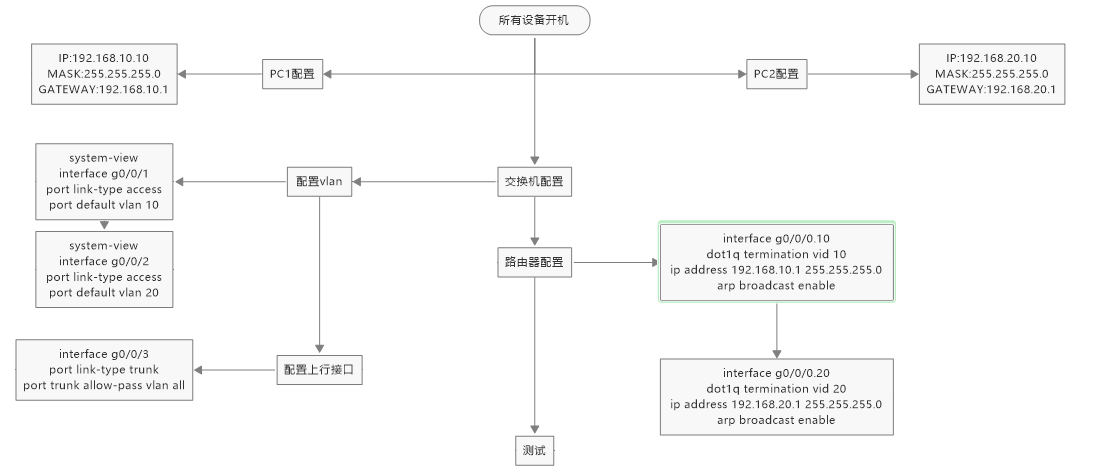
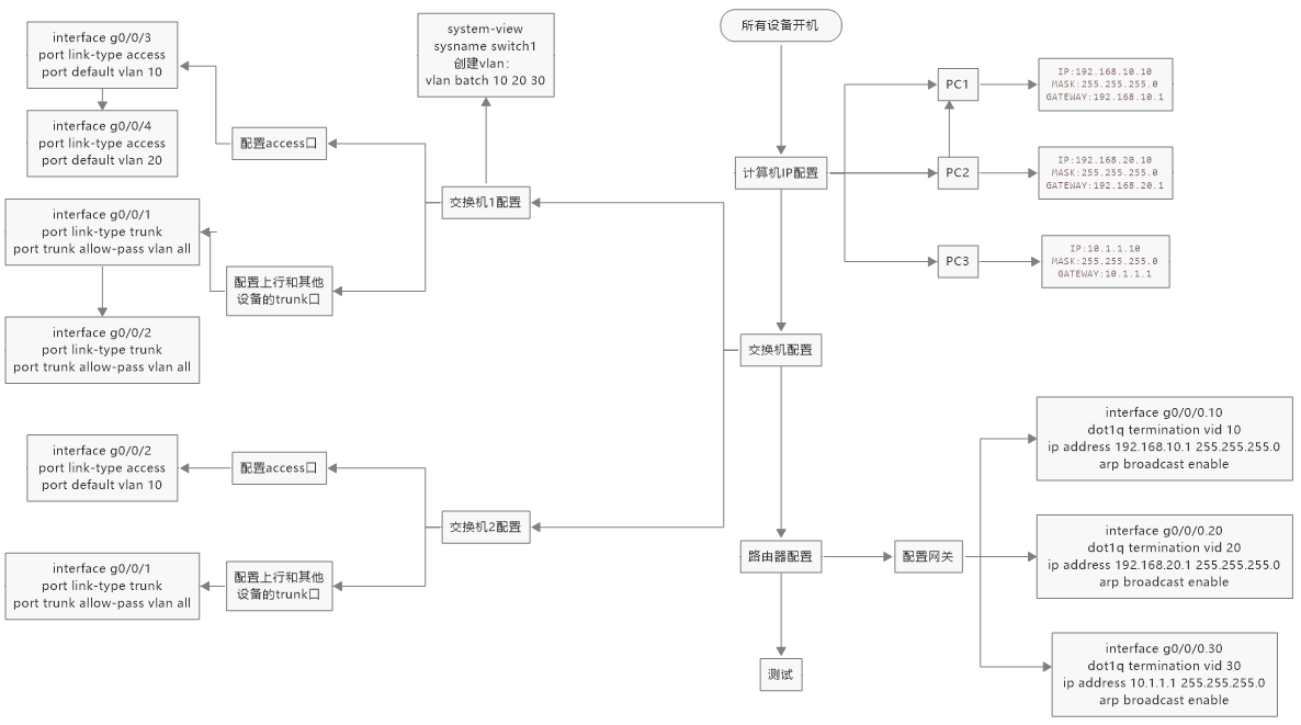
*交换机配置* <Huawei>system-view Enter system view, return user view with Ctrl+Z. [Huawei]sysname switch1 [switch1]info-center source ds channel 0 log state off trap state off [switch1]vlan batch 10 20 Info: This operation may take a few seconds. Please wait for a moment...done. [switch1]interface g0/0/1 [switch1-GigabitEthernet0/0/1]port link-type access [switch1-GigabitEthernet0/0/1]port default vlan 10 [switch1-GigabitEthernet0/0/1]quit [switch1]interface g0/0/2 [switch1-GigabitEthernet0/0/2]port link-type access [switch1-GigabitEthernet0/0/2]port default vlan 20 [switch1-GigabitEthernet0/0/2]quit [switch1]interface g0/0/3 [switch1-GigabitEthernet0/0/3]port link-type trunk [switch1-GigabitEthernet0/0/3]port trunk allow-pass vlan all [switch1-GigabitEthernet0/0/3]quit [switch1]
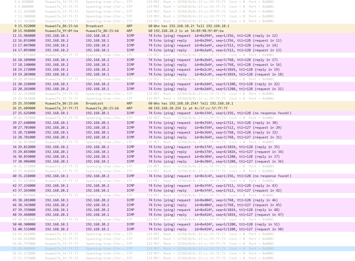
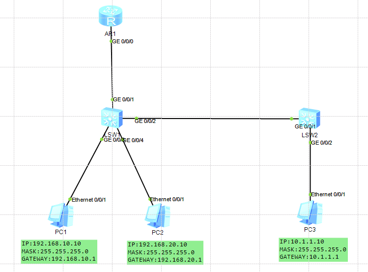
*路由器配置* The device is running! <Huawei>system-view Enter system view, return user view with Ctrl+Z. [Huawei]sysname r1 [r1]interface g0/0/0.10 [r1-GigabitEthernet0/0/0.10]dot1q termination vid 10 [r1-GigabitEthernet0/0/0.10]ip address 192.168.10.1 255.255.255.0 [r1-GigabitEthernet0/0/0.10] Dec 9 2023 20:47:22-08:00 r1 %%01IFNET/4/LINK_STATE(l)[0]:The line protocol IP on the interface GigabitEthernet0/0/0.10 has entered the UP state. [r1-GigabitEthernet0/0/0.10]arp broadcast enable [r1-GigabitEthernet0/0/0.10]quit [r1]interface g0/0/0.20 [r1-GigabitEthernet0/0/0.20]dot1q termination vid 20 [r1-GigabitEthernet0/0/0.20]ip address 192.168.20.1 255.255.255.0 Dec 9 2023 20:48:15-08:00 r1 %%01IFNET/4/LINK_STATE(l)[1]:The line protocol IP on the interface GigabitEthernet0/0/0.20 has entered the UP state. [r1-GigabitEthernet0/0/0.20]arp broadcast enable [r1-GigabitEthernet0/0/0.20]quit [r1]
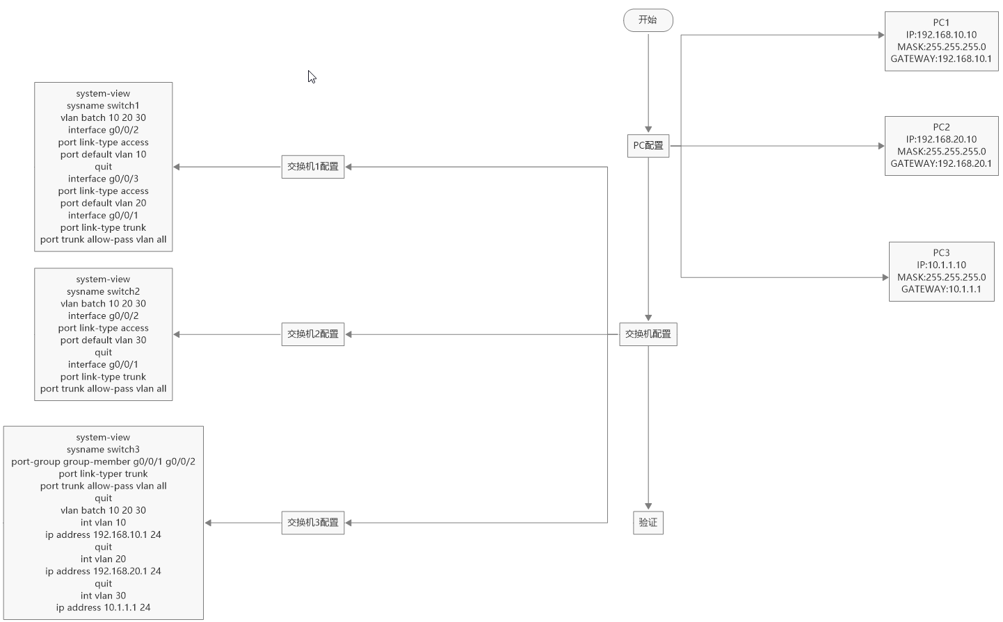
*交换机1配置*
<Huawei>system-view
Enter system view, return user view with Ctrl+Z.
[Huawei]sysname switch1
[switch1]info-center source ds channel 0 log state off trap state off
[switch1]vlan batch 10 20 30
Info: This operation may take a few seconds. Please wait for a moment...done.
[switch1]interface g0/0/3
[switch1-GigabitEthernet0/0/1]port link-type access
[switch1-GigabitEthernet0/0/1]port default vlan 10
[switch1-GigabitEthernet0/0/1]quit
[switch1]interface g0/0/4
[switch1-GigabitEthernet0/0/2]port link-type access
[switch1-GigabitEthernet0/0/2]port default vlan 20
[switch1-GigabitEthernet0/0/2]quit
[switch1]interface g0/0/1
[switch1-GigabitEthernet0/0/3]port link-type trunk
[switch1-GigabitEthernet0/0/3]port trunk allow-pass vlan all
[switch1-GigabitEthernet0/0/3]quit
[switch1]interface g0/0/2
[switch1-GigabitEthernet0/0/3]port link-type trunk
[switch1-GigabitEthernet0/0/3]port trunk allow-pass vlan all
[switch1-GigabitEthernet0/0/3]quit
[switch1]
1
2
3
4
5
6
7
8
9
10
11
12
13
14
15
*交换机2配置*
<Huawei>system-view
Enter system view, return user view with Ctrl+Z.
[Huawei]sysname switch1
[switch1]info-center source ds channel 0 log state off trap state off
[switch1]vlan batch 10 20 30
Info: This operation may take a few seconds. Please wait for a moment...done.
[switch1]interface g0/0/2
[switch1-GigabitEthernet0/0/1]port link-type access
[switch1-GigabitEthernet0/0/1]port default vlan 30
[switch1-GigabitEthernet0/0/1]quit
[switch1]interface g0/0/1
[switch1-GigabitEthernet0/0/3]port link-type trunk
[switch1-GigabitEthernet0/0/3]port trunk allow-pass vlan all
[switch1-GigabitEthernet0/0/3]quit
*交换机1配置*
The device is running!
<Huawei>system-view
[Huawei]sysname switch1
[switch1]info-center source ds channel 0 log state off trap state off
[switch1]vlan batch 10 20 30
Info: This operation may take a few seconds. Please wait for a moment...done.
[switch1]interface g0/0/2
[switch1-GigabitEthernet0/0/2]port link-type access
[switch1-GigabitEthernet0/0/2]port default vlan 10
[switch1-GigabitEthernet0/0/2]quit
[switch1]interface g0/0/3
[switch1-GigabitEthernet0/0/3]port link-type access
[switch1-GigabitEthernet0/0/3]port default vlan 20
[switch1-GigabitEthernet0/0/3]quit
[switch1]interface g0/0/1
[switch1-GigabitEthernet0/0/1]port link-type trunk
[switch1-GigabitEthernet0/0/1]port trunk allow-pass vlan all
1
2
3
4
5
6
7
8
9
10
11
12
13
14
*交换机2配置*
<Huawei>system-view
[Huawei]info-center source ds channel 0 log state off trap state off
[Huawei]sysname switch2
[switch2]vlan batch 10 20 30
Info: This operation may take a few seconds. Please wait for a moment...done.
[switch2]interface g0/0/2
[switch2-GigabitEthernet0/0/2]port link-type access
[switch2-GigabitEthernet0/0/2]port default vlan 30
[switch2-GigabitEthernet0/0/2]quit
[switch2]interface g0/0/1
[switch2-GigabitEthernet0/0/1]port link-type trunk
[switch2-GigabitEthernet0/0/1]port trunk allow-pass vlan all
[switch2-GigabitEthernet0/0/1]quit
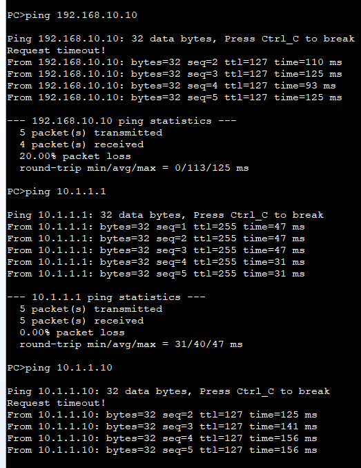
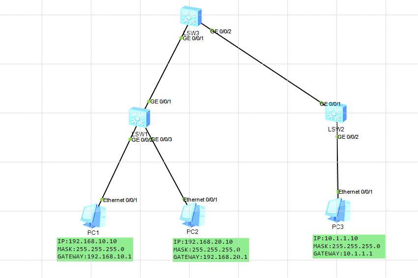
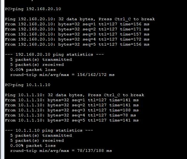
*交换机3配置*
The device is running!
<Huawei>system-view
[Huawei]info-center source ds channel 0 log state off trap state off
[Huawei]sysname switch3
[switch3]port-group group-member g0/0/1 g0/0/2
[switch3-port-group]port link-type trunk
[switch3-GigabitEthernet0/0/1]port link-type trunk
[switch3-GigabitEthernet0/0/2]port link-type trunk
[switch3-port-group]port trunk allow-pass vlan all
[switch3-GigabitEthernet0/0/1]port trunk allow-pass vlan all
[switch3-GigabitEthernet0/0/2]port trunk allow-pass vlan all
[switch3]vlan batch 10 20 30
Info: This operation may take a few seconds. Please wait for a moment...done.
[switch3]int vlan 10
[switch3-Vlanif10]
Dec 18 2023 22:42:00-08:00 switch3 %%01IFNET/4/IF_STATE(l)[0]:Interface Vlanif10
 has turned into UP state.
[switch3-Vlanif10]ip address 192.168.10.1 24
[switch3-Vlanif10]
Dec 18 2023 22:42:17-08:00 switch3 %%01IFNET/4/LINK_STATE(l)[1]:The line protoco
l IP on the interface Vlanif10 has entered the UP state.
[switch3-Vlanif10]quit
[switch3]int vlan 20
[switch3-Vlanif20]
Dec 18 2023 22:42:27-08:00 switch3 %%01IFNET/4/IF_STATE(l)[2]:Interface Vlanif20
 has turned into UP state.
[switch3-Vlanif20]ip address 192.168.20.1 24
[switch3-Vlanif20]
Dec 18 2023 22:42:36-08:00 switch3 %%01IFNET/4/LINK_STATE(l)[3]:The line protoco
l IP on the interface Vlanif20 has entered the UP state.
[switch3-Vlanif20]quit
[switch3]int vlan 30
[switch3-Vlanif30]
Dec 18 2023 22:42:48-08:00 switch3 %%01IFNET/4/IF_STATE(l)[4]:Interface Vlanif30
 has turned into UP state.
[switch3-Vlanif30]ip address 10.1.1.1 24
[switch3-Vlanif30]
Dec 18 2023 22:42:56-08:00 switch3 %%01IFNET/4/LINK_STATE(l)[5]:The line protoco
l IP on the interface Vlanif30 has entered the UP state.
[switch3-Vlanif30]